Mini Golf
Posted: May 1, 2025
Introduction
Last summer I went with a few coworkers to a place called Puttshack. It's kind of a food area with several mini-golf courses setup with electronics all over. Each player got their own ball and when it's placed on the tee the ball is detected. A big screen shows the player's name, their computed score every time the ball is hit, and when the ball falls in the hole it shows the player is done.
Being engineers, there was a discussion how the system works. This turned into me going home and ordering parts.
Not being sure how Puttshack really does their system (very impressive btw.. was a lot of fun). What I came up with was an RFID tag and a Bluetooth beacon with a 3 axis accelerometer. ESP32's both at the tee and at the hole communicate over WiFi. When a ball is placed on the tee, an RFID reader detects tha ball and tells the hole circuit which player is starting.
Connected to the hole circuit is a 4 line LCD (SerLCD from SparkFun) which has an RGB backlight. So if the backlight is red, it indicates no connection from the tee. Blue means there is a connection but no ball is in play. Green means a ball is in play.
The system is designed for 3 distinct balls / players with the RFID tags and Bluetooth ID's hardcoded.
More in depth description of everything further on this page along with source code that could be helpful for anyone trying to deal with these RFID tag readers.
Videos
YouTube: https://youtu.be/_FQiqLAyQyY
Here's a video of the system. The video is filmed at work where a co-worker helped me by hitting a ball around. It's cut up so not all the hits to the ball is shown, but this should give a good idea of how the game worked. During lunch time a few coworkers took shots at the game, but I didn't end up taking more video. I was kind of expecting someone to complain about the shoebox obstacle, something like "it's not even possible to hit a ball through that" where my answer was going to be "not my problem"... but one of my coworkers hit the ball directly from the tee straight through the opened door on the box.
Very conveniently, there is a temporary hole in the floor near my desk at work where the "ball in the hole" detection switch was placed.
YouTube: https://youtu.be/FCKgIbiCu_U
Above is a modification to the Mini Golf circuit that turns it into an RC Car racing circuit. A laser detector was added to the ESP32 which is used to know if the car is breaking the start / end line. The ESP32 makes sure the car doesn't start early and times 3 laps.
Explanation
The project breaks down to several smaller projects put together:
- RFID tag reader (PN532).
- Bluetooth beacon (InPlay IN100) and ESP32 code to listen to it.
- LCD display.
- WiFi between two ESP32's.
- Detect ball in the hole.
- ATtiny85 circuit with servo motor and LED eyes moving a door.
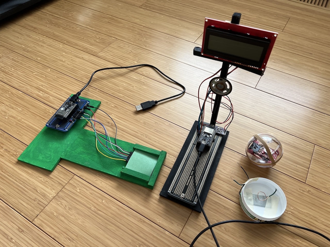
The picture above shows all the different parts of main golf circuit. The wooden structure painted green is the tee circuit which has an RFID reader with a sheet of green paper over it connected by SPI to an ESP32 board. The black painted wooden structure has an ESP32, a cheap sound amplifier board, a speaker, and an LCD display. To the right is one of the balls with the Bluetooth beacon and below that is the "ball is in the hole" detector. There is a deeper explanation lower on this page.
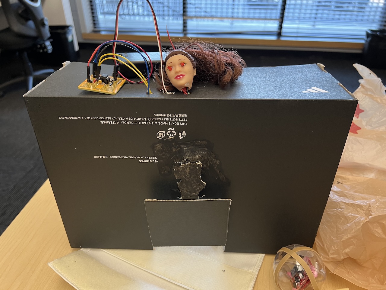
This picture shows a shoebox which is used an obstacle to hit the ball either around or through it when the door is opened. An Atmel ATtiny85 microcontroller connected to a servo motor will keep the door shut for 8 seconds and then open it for 3. A doll head with LED eyes was added to the circuit just to creep people out.
RFID Tag
The first part of this project was getting an RFID reader to work. On Amazon, I found a couple kits for around $10 that both came with 6 tags and 3 readers. One reader was based on an MFRC522 chip while the other was a PN532. The MFRC522 chip seemed simpler so I started with that and wow I wrong. Maybe it really was simpler but after struggling with the documentation and even looking at some Arduino code for it, it was time to just move on.
The PN532 was a little better with documentation, but had some... quirks in there too. One of the bigest quirks with this chip is the way SPI was implemented on it. The chip itself supports UART, i2c,and SPI, but I almost always use SPI since it's typically easier to write software for. Unfortunately, there was a hardware design decision to do the SPI least significant bit first. Chips like the MSP430, which I originally used to test this board, has hardware support for least significant bit first, but it seems the ESP32 does not. I ended up having to do a software SPI for this part of the system. The SPI protocol on this chip also required an extra byte for some reason. The extra byte and the part that says SPI is LSb first is kind of hidden in a sea of text of the PDF file.Incase there was a need for this RFID tag reader for a future project I made a small PN532 page trying to document a little further on how the chip works. I also added the original MSP430 test code that was used to prove this board works to this git repo.
Amazon also sells RFID stickers that luckily came with a unique number programmed in each of them. Because of that, the "write" feature of the PN532 wasn't needed.
The hope was that a single RFID tag in the ball could be detected no matter how the ball was placed on the tee. The reality was the tag had to be fairly close to the RFID reader. This meant that the ball always had to be placed tag down. Being inside the plastic and maybe even the rubber bands and paper over the sensor, it sometimes had trouble reading those tags.
Bluetooth Beacon
SparkFun sells a module called a NanoBeacon based on an IN100 chip. By the name it sounded like it was something similiar to AirTags, which I believe are able to give some sense of "distance". The original thought was two have two ESP32 devices listening for the beacon. If either device detects a change in distance it would be considered a hit. The beacon does give a "power" level, but using a mobile phone with an app, those values were kind of all over the place.
The next thought was either a 3 axis accelerometer, gyroscope, or some kind of combination. If the values are changing it must be moving. Gyroscopes seem to be kind of expensive, so a trip to Amazon found three analog 3-axis accelerometers for $20.
The NanoBeacons themselves were pretty cheap at only around $5 a piece when I got them but they seem to have gone up in price to over $6. Sad.
The IN100 chip has the ability to read 3 analog inputs and output the ADC values at intervals. For this project each IN100 chip in each ball is programmed to emit the values every 500ms. The ESP32 on the base station listens to Bluetooth and if it notices a significant change in values it registers as "the ball is moving". When the values stabilize the device increments the hit counter and emits a beeping noise.
The IN100 is configured with a program called NanoBeaconConfigTool. Some screenshots below show some of the settings that were used for this project.
![]()
The picture above shows the 3 ADC channels setup in the NanoBeacon. NOTE: The 3-axis accelerometers output 3v while according to the documentation for the IN100, the ADC requires a lower voltage. Some voltage divider was used to scale down the voltage.
![]()
The advertising config is set up for 500ms intervals and also an address of 06:05:04:03:02:01 for the first ball. The second ball is setup as 06:05:04:03:02:02 and the third is 06:05:04:03:02:03. The ESP32 program uses the last byte to figure out which ball is currently broadcasting.
![]()
The broadcast data is the 3 ADC values along with 0xff 0xff as some extra data to make it easier to read in the debug tool (the phone app that listens for Bluetooth data).
![]()
Here is a more human readable view of what the data will end up looking like.
Plastic Balls and Club
Since the NanoBeacons weren't going to fit inside any kind of real golf ball, a set of plastic "decoration" balls were used. There's a pretty big selection of these balls online at all different sizes. Measuring the diagnol size of the board, the proper size was picked out.
On the inside of each ball is an RFID tag sticker. Each ball is labeled 1 to 3 and rubber bands are used to help keep it together. After coworkers took turns hitting balls around the course, one of those balls did get cracked.
To hold the circuitry in place a little better, a small piece of Silly Putty was added to the corner of the circuit board. It also gives the ball a nice fruity smell... for some reason they added some kind of stink to the putty.
The club used to hit the balls around is simply a dowel rod glued to small block of wood. Some soft packing material is used to dampen the collision between the ball and club which is held together by rubber bands.
WiFi and LCD Display
To speed up development of the WiFi, the source code was directly copied from the Drag Racing Tree project. The drag racing tree had a built in web server so that a computer could connect and show scores. All that code was removed, but it would probably be super cool to have that feature for the golf game. It would make it a lot more similar to what Puttshack does, but it just adds complexity that seemed a little much at this time.
The display used here is a 4 line SerLCD display that was used for an earlier W65C832 project. The display will show a background color of red if the tee circuit isn't connected, blue when it is connected, and green if a ball is in play. The bottom line of the display will show the current player's hit count while the upper 3 lines show player 1 to 3's last score.
Hole
This was the last piece added to the system. There were a bunch of different ways this piece could have been done. Some early considerations were an ultrasonic distance detector or trying to put IR across the ball in the hole to see if the "beam" is broken. In the end it seemed easier to just make a homemade switch using a small piece of metal at the bottom and a stripped copper wire bent into a loop above it. When a ball falls on the looped wire it would make contact with the metal at the bottom. Another idea was to try to use an actual push button, but I didn't have any push buttons that would make contact with the light weight of these balls.
Source code
git clone https://github.com/mikeakohn/mini_golf.git
Copyright 1997-2026 - Michael Kohn
